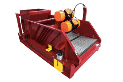
A shale shaker’s position of the drive system of with two unbalanced vibration exciters and a given vibration trajectory is determined using systems of motion equations. This drive system is analyzed for an industrial prototype of shale shaker. The result is adjusted for the constraint of the dynamic load-carrying capacity of the bearings in a shaker.
Motion equations of the frame of a shaker are analyzed in for assigned vibration trajectories. Synthesis of the drive system of the shaker, which provides for an assigned vibration trajectory, is possible when these motion equations are compared with more precisely defined motion equations of the shaker drive.
The more precisely defined motion equations of a shaker drive in terms of the x and y coordinates assume the form:
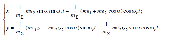
where mΣ is the mass of the vibrating portion of the assembly in kg; mε1 and mε2 are the static moments of the masses of the first and second unbalanced vibration exciters (UVE); α is the difference between the rotational phases of the UVE; ωr and t are the angular velocity and time of the oscillations; and σi is an indicator of the direction of motion of the UVE (when σi = +1, the motion is counterclockwise, and when σi = –1, the motion is clockwise).
Attainment of elliptical trajectories is possible in the case of the opposite (counter) motion of the UVE. Here, σ1σ2 = –1, and the amplitudes Ax and Ay, the phases ϕx and ϕy, and the phase difference ϕyx in the motion equations of the shale shaker drive will then assume the form:

The vibration phases were determined using the arccosZ function (Fig. 1). Among the inverse trigonometric functions, this is the only one that can be differentiated within the interval [–π, +π]. The function makes it possible to determine unambiguously the angle in this interval based on the sign of the sine of the phase. If the sign is “+” or “–”, the upper and lower portions of the curve are utilized, respectively.
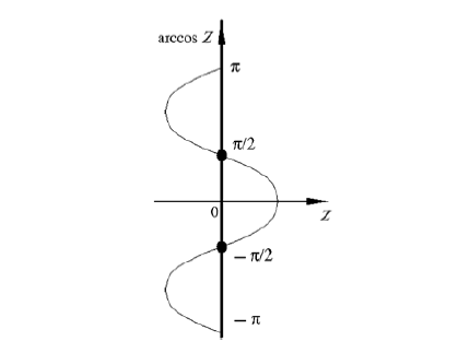
vibration phases.
Using equations of motions of the frame, and equations of motion of the shaker drive, the problem of synthesizing the drive system will be reduced to solution of the following system of equations:

A program incorporating the Newton–Raphson method, which is described in, has been developed in the Matlab medium for numerical solution of system of equations.

The amplitudes Ax0 = 0.0033 m and Ay0 = 0.0023 m, and the difference in the vibration phases ϕyx0 = –0.264 rad
for unbalanced masses with mε1 = 1.89 kg⋅m and mε2 = 1.47 kg⋅m, and α = –1.22 rad. The vibration trajectory is shown in Fig. 2, and corresponds to the computational example cited in [1]. As the directions of motion of the unbalanced masses are reversed (σi = –1; +1), the trajectories are unaltered, but the parameters of the unbalanced masses and their positions are changed: mε1 = 1.47 kg⋅m, mε2 = 1.89 kg⋅m, and α = +1.22 rad.
As is apparent from this example, one of the unbalanced masses should have a static mass moment mεi, which is greater than the maximum allowable (mε)max to ensure the prescribed vibration trajectory. The allowable static mass moment should not exceed 1.34 kg⋅m for a series-produced SV1L shaker with 42312 bearings. It is natural that the longevity of the UVE will be shorter than that required when this moment is greater. In that case, it is necessary to adjust the assigned vibration trajectory to fulfill the condition.
max(mε1, mε2) ≤ (mε)max. (formulas 3)
In adjusting the trajectories, we can preserve the angle of incline β and the ratio of the semi-axes of the ellipse kab = a/b, as well as the direction of motion along the trajectory. If condition (3) is considered with an equal sign, a radical change is required of the problem statement. The computing power of a personal computer enables us to abandon the previous problem statement, and adjust the trajectory by subsequently reducing only the major semi-axis a in intervals Δa until condition is violated. For this purpose, appropriate changes were incorporated in the DissSITO–sintes program. In testing the program based on data of the first example for Δa = 1⋅10–4 m, the following vibration parameters were obtained: Ax = 0.0026 m, Ay = 0.0019 m, ϕyx0 = –0.264 rad, and the parameters of the unbalanced masses mε1 = 1.51 kg⋅m, mε2 = 1.18 kg⋅m, and α = –1.22 rad. The adjusted vibration trajectory is shown in Fig. 2, and falls within the previously assigned ellipse.
the expression for determination of the difference α in the rotational phases of the unbalanced masses permits calculation only of the sum of the position angles of the unbalanced masses (Fig. 3):
δ1 + δ2 = σ2α – σ2 arcsin (ΔM1(t)/W), (formulas 4)
where δ1 and δ2 are the angles between the horizontal and vector connecting the center of gravity of the moving portion and the center of rotation of the ith UVE, ΔM1(t) is the excess moment of the UVE in N⋅m, and W is the absolute value of the vibrational moment in N⋅m.
The excess moment ΔM1(t) in expression is the interference generated in synthesizing the trajectories, which in principle, can be reduced to zero by appropriate technical means of automation; hereinafter, we will therefore consider that the sum of the angles δ1 and δ2 from expression corresponds to the expression:
δ1 + δ2 = σ2α. (formulas 5)
For the example cited, δ1 + δ2 = +1.22 rad. Angular oscillations of the shale shaker frame, which are described in [6] by the following expression, may develop during steady motion of the shale shaker:
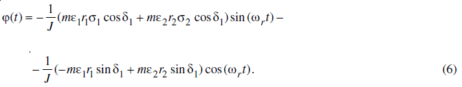
Angular oscillations of the shaker frame are unacceptable, since being superposed onto the linear vertical oscillations, they distort the synthesized vibration trajectory, particularly heavily at the ends of the frame.
Analysis of expression indicates that no angular oscillations are present for the condition.
mε1r1 = mε2r2, (formulas 7)
where r1 and r2 are the radius-vectors from the center of gravity of the moving portion to the center of rotation of the first and second unbalanced masses.

Condition is a basic condition of the synthesis of vibration trajectories, which should be strictly observed in the
design of a shale shaker.
When there is no overload on the electric motors of the UVE drives, the condition required for stable motion of the shale shaker takes on the following form:
![]()
where Mnom is the nominal moment of the UVE in N⋅m.
The equal sign in condition corresponds to the minimal lengths of the radius-vectors r1 and r2. Considering, we obtain a second constraint on the parameters of the shale shaker:

where J is the moment of inertia of the vibrating portion of the shaker in kg⋅m².
Formulas for determination of the minimum lengths of the radius-vectors r1min and r2min, which are sufficient for motion stability of the shaker frame within the allowable range of variation in the moments of resistances, can be derived from expression for condition:

Calculations based on formulas and for J = 220 kg⋅m2 and Mnom = 10 N⋅m make it possible to obtain the minimum values r1min = 0.224 m and r2min = 0.301 m. The actual values of these radius-vectors are substantially higher than the minimum values owing to the clearance dimensions of the UVE and their bearing structures; condition (8) is therefore always satisfied.
The problem of synthesizing the position of the drive of a shale shaker with an assigned vibration frequency is therefore resolved. The inertial and geometric parameters required for the design of a shaker are acquired. Numerical values of the central static moments of the first and second unbalanced masses mε1 and mε2, the length of the radius vectors r1min and r2min, which can be calculated from formulas (10) and (11), and the sum of the angles δ1 and δ2, as defined by formula (5), are a result of the synthesis.
Related posts:
 aipu shale shaker
 Kinematic Law of Solids on a Drilling Fluid Vibrating Screen
 The Different Between Desander Cone And Desilter Cone
 Drilling Mud Problems And Treatment
 Mud Cleaner
 THE IMPORTANCE OF SOLIDS CONTROL
 ELEMENTAL COMPOSITION OF AIRBORNE DUST IN THE SHALE SHAKER HOUSE DURING AN OFFSHORE DRILLING OPERATI...
 Mud Mixing System for Fracturing Sand Slurry
